Note
This technote is not yet published.
Fibers and copper deployed at La Serena
1 Introduction
The purpose of this document is to provide information related to the installation, materials used, network point areas, and the number of fiber filaments used per floor. This documentation also reflects how the physical network of the new office building in La Serena is built by putting an emphasis on the fact that the project is still undergoing construction and will undergo continuous changes in the near future. These changes include additional network points or removing those that are already in place. The materials used for this project were all selected based on their quality and technical properties so that the project can operate at maximum performance in the operations phase.
2 Current Deployment
The following documentation provides information related to the copper and fiber optic connections installed both in the first and second floor of the new office building, please note that before any of these activities took place various meetings and conversations were held with IT personnel and project staff in which eventually a consensus was made and it was determined that each office will support up to 6 data point connections for use. With this said, there are some areas that are considered to be exceptions to course, these areas include the visiting room and the Rubin Observatory control room. Both of these areas have the largest amount of data points both mounted on the floor and walls. When the construction of the building was finished, some of these network points that were already installed had undergone some modifications both by requests from personnel and by locations that required a change.
Note: Both first and second floor, all network points located in these areas reach their corresponding technical room.
2.1 Materials Used
To carry out this activity the folowing materials were selected and used:
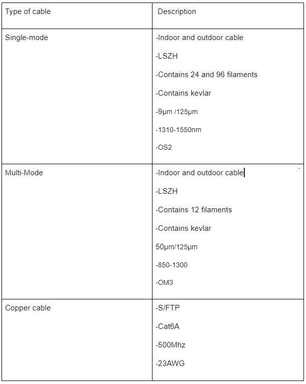
2.1.1 Fiber
Single-mode and Multi-mode fiber was selected and installed in the technical rooms due to their properties. Single-mode fiber provides an unlimited transimision rate, all of Rubin equipment are connected with this type of fiber in the new office building. In regard to the Multi-mode fiber mentioned earlier, this fiber was also setup and installed for the network devices the require the use of it.
For each of these technical rooms, IT considered installing both 48 single-mode and 48 multi-mode optical fibers in an optical terminal that is located in the upper part of the pedestal rack for each one of these technical rooms. This fiber will only be used for the equipment that functions as a transmitter (TX) and receiver (RX).
2.1.2 Copper
It is also noted that UTP S/FTP cables were also selected due to the cable properties and ability to work at 10GBASE-T speeds. All network points were installed with this type of cable, both the access points and telephony connection systems. In regard to end-user devices, UTP CAT6 was setup.
In regard to the data point connections, these are different for both the first floor and the second floor hence they are similar but not the same request.
2.1.3 Component Features
This documentation illustrates the various network points and their locations (Floors, Walls, Ceilings).
3 Areas of interest
- First Floor
- Second Floor
4 First Floor
The first floor consists of the following characteristics in terms of materials and numbering of the network points.
- 181 Network points in total
- 7 Access Point
All of the fiber optic connections that are fed with a signal in the technical rooms all come from the data center located in rack A1.
4.1 First Floor Image
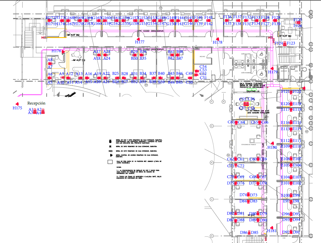
The image shows a letter with the data point number, this letter corresponds to the numbering of the patch panel that connects the data point, for example: 1A to 24A / 25B to 48B / 49C to 72C. etc.)
Please note that these network points are mixed, what this actually means is that these points are not predefined and set to be either data or VoIP. This will depend directly on the requirements made by the staff and the switch’s configuration.
4.2 Technical Room First Floor
The technical room inside the first floor consists of the following characteristics in terms of materials and the numbering used for the network points.
- 181 Network points in total (in the patch panels)
- 8 Patch panel
- 4 48-port switch
- 2 PDUs (primary and backup)
- 1 42U Pedestal Rack
- 1 Optical terminal with 96 optical fibers (48 singlemode OS2 and 48 multimode OM3)
This room also houses the electrical equipment for the entire first floor and and the UPS systems that powers the network equipment.
4.2.1 Technical Room First Floor Images

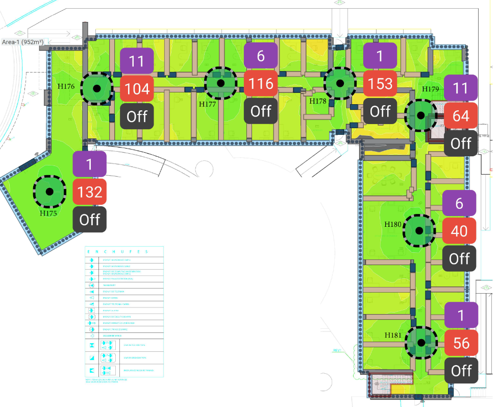
4.3 Data Points / Access Points First Floor
In the first floor, we will find 7 access points installed in the locations instructed by the network engineer in charge. These areas were previously monitored with a program that certified the best locations for the propagation of the signals from these access points.
4.3.1 Data Points Access Point First Floor Image
5 Second Floor
The second floor consists of the following elements in terms of materials and numbering of the various network points.
- 171 Network points in total
- 7 Access points
5.1 Second Floor Image
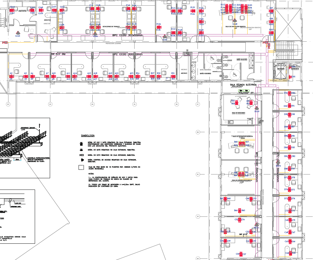
The image shows a letter with a data point number and this letter corresponds to the numbering of the patch panel that connects the data point, for example: 1A to 24A / 25B to 48B / 49C to 72C. etc.)
Please note that these network points are mixed, what this actually means is that these points are not predefined and set to be either data or VoIP. This will depend directly on the requirements made by the staff and the switch’s configuration.
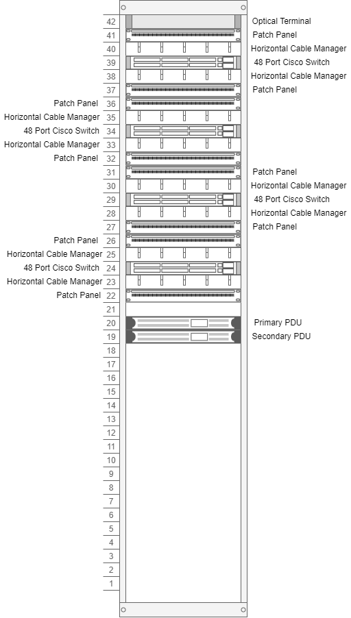
5.2 Technical Room Second Floor
The technical room, located inside the second floor contains the following characteristics in terms of materials and numbering used for the various network points.
- 171 Network points in total (in the patch panels}
- 8 Patch panel
- 4 48-port switch
- 2 PDUs (primary and backup)
- 1 42U Pedestal Rack
- 1 Optical terminal with 96 optical fibers (48 singlemode OS2 and 48 multimode OM3)
This room also houses the electrical equipment for the entire first floor and the UPS systems that power the network equipment.
5.2.1 Technical Room Second Floor Images
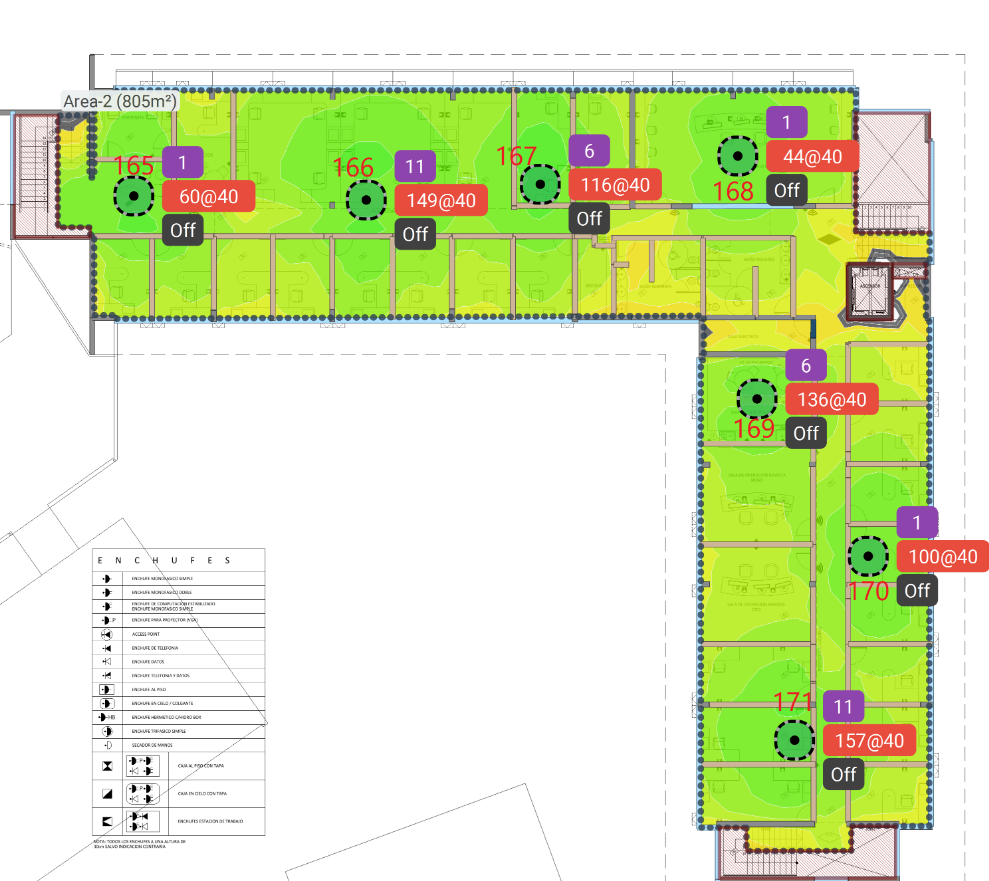
5.3 Data Point Access Point Second Floor
In the first floor of the building, we will find 7 access points installed in the locations assigned by the network engineer. These areas were previously monitored with a program that certified the best locations for the propagation of the signals from these access points.
5.3.1 Data Point Access Point Second Floor
6 Activities planned for FY21
There are currently no activities planned for FY21, the project is already delivered to NOIRLabs IT Team who will be in charge of any future adjustments or changes.
7 Acronyms
| Term | Meaning |
|---|---|
| 10G | 10 Gigabits |
| AP | Access Point |
| Auxtel | Auxiliary Telescope |
| AWG | American Wire Gauge |
| AURA | Associated Universities for Research in Astronomy |
| BDC | Base Data Center |
| CAT | Category |
| DWDM | Dense Wavelength Division Multiplexing |
| FY | Fiscal Year |
| IEEE | Institute of Electrical and Electronics Engineers |
| IT | Information Technology |
| LAB | Laboratory |
| LC | Little Connector or Lucent Connector |
| LSZH | Low smoke zero halogen |
| MM | Multi-mode |
| MHZ | Megahertz |
| OM1 | Optical Multi-mode the number is the CAT of the cable |
| OM3 | Optical Multi-mode the number is the CAT of the cable |
| OS2 | Optical Single-mode the number is the CAT of the cable |
| S/FTP | Shielded/Foiled Twisted Pair |
| SM | Single-mode |
| TX | Transmission |
| UTP | Unshielded Twisted Pair |
| UPC | Ultra Physical Contact |
| UPS | Uninterruptible Power Supply |
| VoIP | Voice Over Internet Protocol |
| µm | Microns |
| nm | Nanometer |